 Skip to content
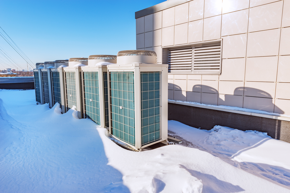
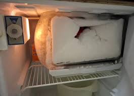
When a refrigeration system drops below freezing, humidity in the air naturally condenses and freezes onto the evaporator coil surface. Left unchecked, this frost turns into a thick layer of ice that acts like insulation, blocking airflow and choking heat transfer. To keep the system running efficiently, you have to melt that ice periodically.
But a Defrost heterst cycle is not as simple as just turning on a heater. For industrial and commercial systems, it requires a precise mechanical choreography to protect the equipment and prevent heat from spoiling the refrigerated space
Here is the exact sequence of a properly engineered refrigeration defrost cycle.
Phase 1: Initiation and Pump-Down
The cycle begins either on a set schedule or when an adaptive controller detects a drop in system efficiency. Before any heat is introduced to the evaporator, the system must handle the refrigerant inside the coil.
- The Liquid Solenoid Closes: The valve supplying liquid refrigerant to the expansion valve shuts down.
- The Pump-Down Cycle: The compressor keeps running, pulling the remaining low-pressure refrigerant out of the evaporator coil and pushing it into the receiver.
- The Purpose: Clearing out the liquid refrigerant is a safety precaution. If you apply heat to a coil filled with cold liquid refrigerant, the liquid will rapidly expand, causing extreme pressure spikes. It can also cause liquid to flood back into the compressor when the cooling cycle restarts, potentially destroying the valves.
Phase 2: System Isolation
Once the pressure drops to a safe level in the evaporator, the compressor shuts down. Next, the system must isolate the cold room or freezer from the heat that is about to be generated.
- Evaporator Fans Shut Off: The fans that circulate air through the cold space are turned off.
- The Purpose: This step prevents the defrost heat from being blown into the refrigerated space, keeping the ambient temperature stable and protecting the stored product. It also prevents steam or moisture from being thrown into the room, which would just turn into frost elsewhere.
Phase 3: The heating Phase
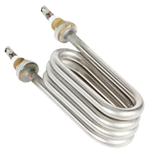
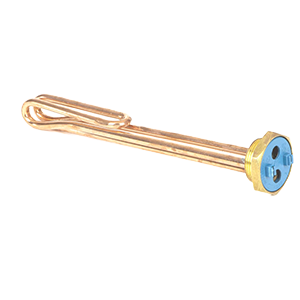
With the system isolated and the coil cleared of refrigerant, the heat source activates. This is typically done through electric heating elements or by redirecting hot gas from the compressor.
- Heat Application: The metal fins and tubes of the evaporator warm up past 0°C.
- Ice Release: The heat breaks the bond between the ice and the aluminum fins. The ice melts from the inside out, collapses, and runs down into a heated drain pan, where it flows out of the room.
Phase 4: Termination and Drip Time
The heating phase does not run indefinitely. A temperature sensor attached to the heaviest frost area of the coil tracks the progress. Once the coil reaches a specific temperature, usually around 4°C to 10°C, the system knows the ice is gone and cuts the heat.
- The Drip Period: After the heat shuts off, the system pauses. The fans and compressor stay off for anywhere from 3 to 5 minutes.
- The Purpose: Drip time allows any remaining water droplets on the fins to slide down into the drain pan. If you skip this step and turn the cooling back on immediately, those droplets will instantly freeze into a fresh layer of ice, ruining the efficiency of the next run cycle.
Phase 5: Re-Initialization and Fan Delay
The final step is safely transitioning back to standard cooling mode.
- Compressor Restarts: The liquid line solenoid opens, and the compressor starts back up to chill the evaporator coil.
- Fan Delay: The evaporator fans remain off for a few extra minutes while the coil temperature drops back down below freezing.
- The Purpose: Keeping the fans off until the coil is completely cold ensures that any lingering moisture on the fins freezes solid onto the metal instead of being blown into the room as a fine mist. Once the coil is cold, the fans kick on, and normal refrigeration resumes.
Engineering Note on Adaptive Controls
Standard systems repeat this entire sequence at fixed time intervals, regardless of whether ice is actually present. Upgrading to adaptive controls allows the system to monitor parameters like fan power draw or temperature differentials, initiating this sequence only when frost physically restricts performance. This reduces total daily runtime and eliminates unnecessary heat injection
